
Narzędzia użytkownika
Spis treści
NanoPi Neo
Schematy GPIO
Cała specyfikacja znajduje się tu: http://wiki.friendlyarm.com/wiki/index.php/NanoPi_NEO
Warto zainstalować
apt install i2c-tools
WiringPI
Instalujemy w systemie bibliotekę do obsługi GPIO: https://github.com/friendlyarm/WiringNP - jest to fork WiringPI dostosowany do NanoPi Neo
Ściągamy pliki:
git clone https://github.com/friendlyarm/WiringNP
W czasie gdy to piszę biblioteka nie rozpoznaje poprawnie urządzenia i należy zmodyfikować źródła. Edytujemy plik wiringPi/boardtype_friendlyelec.c i zmieniamy w nim treść z:
    if (!(f = fopen("/sys/class/sunxi_info/sys_info", "r"))) {
        LOGE("open /sys/class/sunxi_info/sys_info failed.");
        return -1;
    }
Na:
   if (!(f = fopen("/sys/class/sunxi_info/sys_info", "r"))) {
        if (!(f = fopen("/etc/sys_info", "r"))) {
            LOGE("open /sys/class/sunxi_info/sys_info failed.");
            return -1;
        }
    }
Tworzymy plik /etc/sys_info i zapisujemy do niego wartość:
sunxi_platform    : Sun8iw7p1
sunxi_secure      : normal
sunxi_chipid      : 2c21020e786746240000540000000000
sunxi_chiptype    : 00000042
sunxi_batchno     : 1
sunxi_board_id    : 1(0)
Kompilujemy i instalujemy bibliotekę:
cd WiringNP/
chmod 755 build
./build
Sprawdzamy czy sprzęt jest wykrywany poprawnie przez bibliotekę za pomocą polecenia:
# gpio readall
 +-----+-----+----------+------+---+-NanoPi-NEO--+------+----------+-----+-----+
 | BCM | wPi |   Name   | Mode | V | Physical | V | Mode | Name     | wPi | BCM |
 +-----+-----+----------+------+---+----++----+---+------+----------+-----+-----+
 |     |     |     3.3V |      |   |  1 || 2  |   |      | 5V       |     |     |
 |  12 |   8 |  GPIOA12 | ALT5 | 0 |  3 || 4  |   |      | 5V       |     |     |
 |  11 |   9 |  GPIOA11 | ALT5 | 0 |  5 || 6  |   |      | 0v       |     |     |
 | 203 |   7 |  GPIOG11 |  OFF | 0 |  7 || 8  | 0 |  OFF | GPIOG6   | 15  | 198 |
 |     |     |       0v |      |   |  9 || 10 | 0 |  OFF | GPIOG7   | 16  | 199 |
 |   0 |   0 |   GPIOA0 |  OFF | 0 | 11 || 12 | 0 |  OFF | GPIOA6   | 1   | 6   |
 |   2 |   2 |   GPIOA2 |  OFF | 0 | 13 || 14 |   |      | 0v       |     |     |
 |   3 |   3 |   GPIOA3 |   IN | 1 | 15 || 16 | 0 |  OFF | GPIOG8   | 4   | 200 |
 |     |     |     3.3v |      |   | 17 || 18 | 0 |  OFF | GPIOG9   | 5   | 201 |
 |  64 |  12 |   GPIOC0 |  OFF | 0 | 19 || 20 |   |      | 0v       |     |     |
 |  65 |  13 |   GPIOC1 |  OFF | 0 | 21 || 22 | 0 |  OFF | GPIOA1   | 6   | 1   |
 |  66 |  14 |   GPIOC2 |  OFF | 0 | 23 || 24 | 0 |  OFF | GPIOC3   | 10  | 67  |
 +-----+-----+----------+------+---+----++----+---+------+----------+-----+-----+
 | BCM | wPi |   Name   | Mode | V | Physical | V | Mode | Name     | wPi | BCM |
 +-----+-----+----------+------+---+-NanoPi-NEO--+------+----------+-----+-----+

 +-----+----NanoPi-NEO USB/Audio-+----+
 | BCM | wPi |   Name   | Mode | V | Ph |
 +-----+-----+----------+------+---+----+
 |     |     |       5V |      |   | 25 |
 |     |     |  USB-DP1 |      |   | 26 |
 |     |     |  USB-DM1 |      |   | 27 |
 |     |     |  USB-DP2 |      |   | 28 |
 |     |     |  USB-DM2 |      |   | 29 |
 |     |     |    IR-RX |      |   | 30 |
 |  17 |  19 |  GPIOA17 |  OFF | 0 | 31 |
 |     |     |  PCM/I2C |      |   | 32 |
 |     |     |  PCM/I2C |      |   | 33 |
 |     |     |  PCM/I2C |      |   | 34 |
 |     |     |  PCM/I2C |      |   | 35 |
 |     |     |       0V |      |   | 36 |
 +-----+-----+----------+------+---+----+

 +-----+----NanoPi-NEO Debug UART-+----+
 | BCM | wPi |   Name   | Mode | V | Ph |
 +-----+-----+----------+------+---+----+
 |   4 |  17 |   GPIOA4 | ALT5 | 0 | 37 |
 |   5 |  18 |   GPIOA5 | ALT5 | 0 | 38 |
 +-----+-----+----------+------+---+----+
Czujnik temperatury i wilgotności powietrza DHT11
Podłączamy wg schematu:

Czyli:
- pin 15 - GPIO3
- pin 4 - 5V
- pin 6 - GND
Przykładowy program, który korzysta z biblioteki WiringPI mamy tu: https://github.com/nkundu/wiringpi-examples/blob/master/dht11.c
/*
 *  dht11.c:
 *	Simple test program to test the wiringPi functions
 *	DHT11 test
 */

#include <wiringPi.h>

#include <stdio.h>
#include <stdlib.h>
#include <stdint.h>
#define MAXTIMINGS	85
#define DHTPIN		7
int dht11_dat[5] = { 0, 0, 0, 0, 0 };

void read_dht11_dat()
{
	uint8_t laststate	= HIGH;
	uint8_t counter		= 0;
	uint8_t j		= 0, i;
	float	f; /* fahrenheit */

	dht11_dat[0] = dht11_dat[1] = dht11_dat[2] = dht11_dat[3] = dht11_dat[4] = 0;

	/* pull pin down for 18 milliseconds */
	pinMode( DHTPIN, OUTPUT );
	digitalWrite( DHTPIN, LOW );
	delay( 18 );
	/* then pull it up for 40 microseconds */
	digitalWrite( DHTPIN, HIGH );
	delayMicroseconds( 40 );
	/* prepare to read the pin */
	pinMode( DHTPIN, INPUT );

	/* detect change and read data */
	for ( i = 0; i < MAXTIMINGS; i++ )
	{
		counter = 0;
		while ( digitalRead( DHTPIN ) == laststate )
		{
			counter++;
			delayMicroseconds( 1 );
			if ( counter == 255 )
			{
				break;
			}
		}
		laststate = digitalRead( DHTPIN );

		if ( counter == 255 )
			break;

		/* ignore first 3 transitions */
		if ( (i >= 4) && (i % 2 == 0) )
		{
			/* shove each bit into the storage bytes */
			dht11_dat[j / 8] <<= 1;
			if ( counter > 16 )
				dht11_dat[j / 8] |= 1;
			j++;
		}
	}

	/*
	 * check we read 40 bits (8bit x 5 ) + verify checksum in the last byte
	 * print it out if data is good
	 */
	if ( (j >= 40) &&
	     (dht11_dat[4] == ( (dht11_dat[0] + dht11_dat[1] + dht11_dat[2] + dht11_dat[3]) & 0xFF) ) )
	{
		f = dht11_dat[2] * 9. / 5. + 32;
		printf( "Humidity = %d.%d %% Temperature = %d.%d *C (%.1f *F)\n",
			dht11_dat[0], dht11_dat[1], dht11_dat[2], dht11_dat[3], f );
	}else  {
		printf( "Data not good, skip\n" );
	}
}

int main( void )
{
	printf( "Raspberry Pi wiringPi DHT11 Temperature test program\n" );

	if ( wiringPiSetup() == -1 )
		exit( 1 );

	while ( 1 )
	{
		read_dht11_dat();
		delay( 1000 ); /* wait 1sec to refresh */
	}

	return(0);
}
Modyfikujemy linie:
#define DHTPIN 7
Zmieniając na:
#define DHTPIN 3
Jest to nr portu w WiringPI. Można odczytać za pomocą polecenia: „gpio readall” - u mnie akurat podłączony do pinu nr 15 (kolumna Physical) - co daje nr 3 (kolumna wPi).
Kompilujemy:
gcc -Wall -o dht11 dht11.c -lwiringPi -lpthread
Uruchamiamy:
root@nanopineo:~/tests# ./dht11
Raspberry Pi wiringPi DHT11 Temperature test program
Data not good, skip
Data not good, skip
Humidity = 36.0 % Temperature = 23.7 *C (73.4 *F)
Data not good, skip
Humidity = 36.0 % Temperature = 23.8 *C (73.4 *F)
Data not good, skip
Humidity = 36.0 % Temperature = 23.8 *C (73.4 *F)
^C
root@nanopineo:~/tests#
Ctrl C zatrzymujemy program.
Wyświetlacz LCD 2x16 I2C
Podłączamy wg schematu:

Czyli:
- pin 3 - I2C SDA
- pin 5 - I2C SCL
- pin 2 - 5V
- pin 14 - GND
Przykładowy program, który korzysta z biblioteki WiringPI mamy tu: http://www.bristolwatch.com/rpi/code/i2clcd.txt
/*
*
* by Lewis Loflin www.bristolwatch.com lewis@bvu.net
* http://www.bristolwatch.com/rpi/i2clcd.htm
* Using wiringPi by Gordon Henderson
*
*
* Port over lcd_i2c.py to C and added improvements.
* Supports 16x2 and 20x4 screens.
* This was to learn now the I2C lcd displays operate.
* There is no warrenty of any kind use at your own risk.
*
*/

#include <wiringPiI2C.h>
#include <wiringPi.h>
#include <stdlib.h>
#include <stdio.h>

// Define some device parameters
#define I2C_ADDR   0x27 // I2C device address

// Define some device constants
#define LCD_CHR  1 // Mode - Sending data
#define LCD_CMD  0 // Mode - Sending command

#define LINE1  0x80 // 1st line
#define LINE2  0xC0 // 2nd line

#define LCD_BACKLIGHT   0x08  // On
// LCD_BACKLIGHT = 0x00  # Off

#define ENABLE  0b00000100 // Enable bit

void lcd_init(void);
void lcd_byte(int bits, int mode);
void lcd_toggle_enable(int bits);

// added by Lewis
void typeInt(int i);
void typeFloat(float myFloat);
void lcdLoc(int line); //move cursor
void ClrLcd(void); // clr LCD return home
void typeln(const char *s);
void typeChar(char val);
int fd;  // seen by all subroutines

int main()   {

  if (wiringPiSetup () == -1) exit (1);

  fd = wiringPiI2CSetup(I2C_ADDR);

  //printf("fd = %d ", fd);

  lcd_init(); // setup LCD

  char array1[] = "Hello world!";

  while (1)   {

    lcdLoc(LINE1);
    typeln("Using wiringPi");
    lcdLoc(LINE2);
    typeln("Geany editor.");

    delay(2000);
    ClrLcd();
    lcdLoc(LINE1);
    typeln("I2c  Programmed");
    lcdLoc(LINE2);
    typeln("in C not Python.");

    delay(2000);
    ClrLcd();
    lcdLoc(LINE1);
    typeln("Arduino like");
    lcdLoc(LINE2);
    typeln("fast and easy.");

    delay(2000);
    ClrLcd();
    lcdLoc(LINE1);
    typeln(array1);

    delay(2000);
    ClrLcd(); // defaults LINE1
    typeln("Int  ");
    int value = 20125;
    typeInt(value);

    delay(2000);
    lcdLoc(LINE2);
    typeln("Float ");
    float FloatVal = 10045.25989;
    typeFloat(FloatVal);
    delay(2000);
  }

  return 0;

}


// float to string
void typeFloat(float myFloat)   {
  char buffer[20];
  sprintf(buffer, "%4.2f",  myFloat);
  typeln(buffer);
}

// int to string
void typeInt(int i)   {
  char array1[20];
  sprintf(array1, "%d",  i);
  typeln(array1);
}

// clr lcd go home loc 0x80
void ClrLcd(void)   {
  lcd_byte(0x01, LCD_CMD);
  lcd_byte(0x02, LCD_CMD);
}

// go to location on LCD
void lcdLoc(int line)   {
  lcd_byte(line, LCD_CMD);
}

// out char to LCD at current position
void typeChar(char val)   {

  lcd_byte(val, LCD_CHR);
}


// this allows use of any size string
void typeln(const char *s)   {

  while ( *s ) lcd_byte(*(s++), LCD_CHR);

}

void lcd_byte(int bits, int mode)   {

  //Send byte to data pins
  // bits = the data
  // mode = 1 for data, 0 for command
  int bits_high;
  int bits_low;
  // uses the two half byte writes to LCD
  bits_high = mode | (bits & 0xF0) | LCD_BACKLIGHT ;
  bits_low = mode | ((bits << 4) & 0xF0) | LCD_BACKLIGHT ;

  // High bits
  wiringPiI2CReadReg8(fd, bits_high);
  lcd_toggle_enable(bits_high);

  // Low bits
  wiringPiI2CReadReg8(fd, bits_low);
  lcd_toggle_enable(bits_low);
}

void lcd_toggle_enable(int bits)   {
  // Toggle enable pin on LCD display
  delayMicroseconds(500);
  wiringPiI2CReadReg8(fd, (bits | ENABLE));
  delayMicroseconds(500);
  wiringPiI2CReadReg8(fd, (bits & ~ENABLE));
  delayMicroseconds(500);
}


void lcd_init()   {
  // Initialise display
  lcd_byte(0x33, LCD_CMD); // Initialise
  lcd_byte(0x32, LCD_CMD); // Initialise
  lcd_byte(0x06, LCD_CMD); // Cursor move direction
  lcd_byte(0x0C, LCD_CMD); // 0x0F On, Blink Off
  lcd_byte(0x28, LCD_CMD); // Data length, number of lines, font size
  lcd_byte(0x01, LCD_CMD); // Clear display
  delayMicroseconds(500);
}
Szukamy linię:
#define I2C_ADDR 0x27 // I2C device address
I upewniamy się, że nasz kontroler I2C ma ten sam adres. Sprawdzić możemy to poleceniem:
# i2cdetect -y 0
     0  1  2  3  4  5  6  7  8  9  a  b  c  d  e  f
00:          -- -- -- -- -- -- -- -- -- -- -- -- --
10: -- -- -- -- -- -- -- -- -- -- -- -- -- -- -- --
20: -- -- -- -- -- -- -- 27 -- -- -- -- -- -- -- --
30: -- -- -- -- -- -- -- -- -- -- -- -- -- -- -- --
40: -- -- -- -- -- -- -- -- -- -- -- -- -- -- -- --
50: -- -- -- -- -- -- -- -- -- -- -- -- -- -- -- --
60: -- -- -- -- -- -- -- -- -- -- -- -- -- -- -- --
70: -- -- -- -- -- -- -- --
Kompilujemy:
gcc -Wall -o i2clcd i2clcd.c -lwiringPi -lpthread
Po uruchomieniu na wyświetlaczu powinny pojawić się napisy - jeśli się nie pojawiają to może wystarczy wyregulować ekran pokrętłem za pomocą śrubokręta.
Przycisk
Podłączamy wg schematu:

Czyli:
- pin 24 - GPIO 10
- pin 20 - GND
Przykładowy program, który korzysta z biblioteki WiringPI mamy tu: https://www.waveshare.com/wiki/Raspberry_Pi_Tutorial_Series:_External_Button
#include <stdio.h>
#include <wiringPi.h>

char KEY = 10;

int main()
{
    if (wiringPiSetup() < 0)return 1 ;
    // Sets the pin as input.
    pinMode(KEY,INPUT);
    // Sets the Pull-up mode for the pin.
    pullUpDnControl(KEY, PUD_UP);
    printf("Key Test Program!!!\n");
    while(1)
    {
        if (digitalRead(KEY) == 0)
        {
            printf ("KEY PRESS\n") ;
            // Returns the value read at the given pin. It will be HIGH or LOW (0 or 1).
            while(digitalRead(KEY) == 0)
                delay(100);
        }
        delay(100);
    }
}
Gdzie linia:
char KEY = 10;
Jest to nr portu w WiringPI. Można odczytać za pomocą polecenia: „gpio readall” - u mnie akurat podłączony do pinu nr 24 (kolumna Physical) - co daje nr 10 (kolumna wPi).
Kompilujemy:
gcc -Wall ./button.c -o ./button -lwiringPi -lpthread
I uruchamiamy:
# ./button
Key Test Program!!!
KEY PRESS
KEY PRESS
KEY PRESS
KEY PRESS
KEY PRESS
KEY PRESS
KEY PRESS
^C
Dioda
Podłączamy wg schematu:
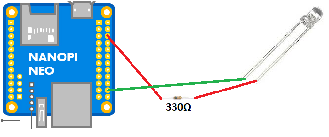
Czyli:
- pin 22 - GPIO 6
- pin 6 - GND (nóżka krótsza)
Przykładowy program, który korzysta z biblioteki WiringPI mamy tu: https://www.waveshare.com/wiki/Raspberry_Pi_Tutorial_Series:_External_Button
#include <wiringPi.h>

#define DIODE 6

int main (void)
{
  wiringPiSetup () ;
  pinMode (DIODE, OUTPUT) ;
  for (;;)
  {
    digitalWrite (DIODE, HIGH) ; delay (500) ;
    digitalWrite (DIODE,  LOW) ; delay (500) ;
  }
  return 0 ;
}
Gdzie linia:
#define DIODE 6
Jest to nr portu w WiringPI. Można odczytać za pomocą polecenia: „gpio readall” - u mnie akurat podłączony do pinu nr 22 (kolumna Physical) - co daje nr 6 (kolumna wPi).
Kompilujemy:
gcc -Wall ./diode.c -o ./diode -lwiringPi -lpthread
Po uruchomieniu dioda powinna migać.
Dioda RGB
Podłączamy wg schematu:
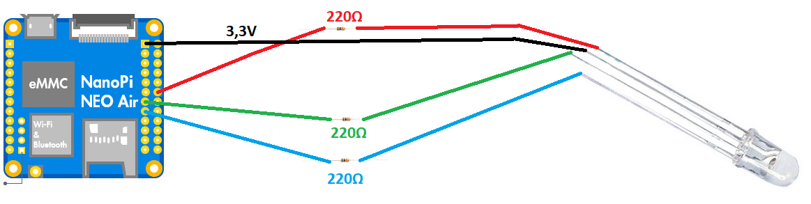
Czyli:
- pin 1 - 3,3V
- pin 12 - GPIO1
- pin 13 - GPIO2
- pin 15 - GPIO3
Przykładowy program, który korzysta z biblioteki WiringPI mamy tu: https://www.admfactory.com/rgb-led-on-raspberry-pi-using-c/
#include <wiringPi.h>
#include <softPwm.h>
#include <stdio.h>

#define LedPinRed    1
#define LedPinGreen  2
#define LedPinBlue   3

const int colors[] = {0xFF0000, 0x00FF00, 0x0000FF, 0xFFFF00, 0x00FFFF, 0xFF00FF, 0xFFFFFF, 0x9400D3};

int map(int x, int in_min, int in_max, int out_min, int out_max)
{
        return (x -in_min) * (out_max - out_min) / (in_max - in_min) + out_min;
}

void ledInit(void)
{
        softPwmCreate(LedPinRed,  0, 100);  //create a soft pwm, original duty cycle is 0Hz, range is 0~100
        softPwmCreate(LedPinGreen,0, 100);
        softPwmCreate(LedPinBlue, 0, 100);
}

void ledColorSet(int color)        //set color, for example: 0xde3f47
{
        int r_val, g_val, b_val;

        r_val = (color & 0xFF0000) >> 16;  //get red value
        g_val = (color & 0x00FF00) >> 8;   //get green value
        b_val = (color & 0x0000FF) >> 0;   //get blue value

        r_val = map(r_val, 0, 255, 0, 100);    //change a num(0~255) to 0~100
        g_val = map(g_val, 0, 255, 0, 100);
        b_val = map(b_val, 0, 255, 0, 100);

        softPwmWrite(LedPinRed,   100 - r_val);  //change duty cycle
        softPwmWrite(LedPinGreen, 100 - g_val);
        softPwmWrite(LedPinBlue,  100 - b_val);
}

int main(void)
{
        int i;

        if(wiringPiSetup() < 0) { //when initialize wiringPi failed, print message to screen
                printf("setup wiringPi failed !\n");
                return -1;
        }

        ledInit();

        while(1) {
                for(i = 0; i < sizeof(colors)/sizeof(int); i++) {
                        ledColorSet(colors[i]);
                        delay(1000);
                }
        }
        return 0;
}
Gdzie linie:
#define LedPinRed    1
#define LedPinGreen  2
#define LedPinBlue   3
Są to nr portów w WiringPI. Można odczytać je za pomocą polecenia: „gpio readall” - u mnie akurat podłączone do pinów nr 12, 13, 15 (kolumna Physical) - co daje nr 1, 2, 3 (kolumna wPi).
Kompilujemy:
gcc -Wall ./diodergb.c -o ./diodergb -lwiringPi -lpthread
Po uruchomieniu dioda powinna migać na różne kolory.
Narzędzia strony
